I INTRODUCTION Bridge (structure), structure designed to provide continuous passage over an obstacle. Bridges commonly carry highways, railroad lines, and pathways over obstacles such as waterways, deep valleys, and other transportation routes. Bridges may also carry water, support power cables, or house telecommunications lines.
Some special types of bridges are defined according to function. An overpass allows one transportation route, such as a highway or railroad line, to cross over another without traffic interference between the two routes. The overpass elevates one route to provide clearance to traffic on the lower level. An aqueduct transports water. Aqueducts have historically been used to supply drinking water to densely populated areas. A viaduct carries a railroad or highway over a land obstruction, such as a valley.
The earliest bridges were simple structures created by spanning a gap with timber or rope. Designs became more complex as builders developed new construction methods and discovered better materials. The stone arch was the first major advance in bridge design. It was used by the ancient Greeks, Etruscans, and Chinese (see Arch and Vault). The Romans perfected arch design, using arches to build massive stone bridges throughout the Roman Empire. Stone arch construction remained the premier bridge design until the introduction of the steam locomotive in the early 19th century.
Between 1830 and 1880, as railroad building expanded throughout the world, bridge design and construction also evolved to carry these heavy vehicles over new obstacles. Designers experimented with a wide variety of bridge types and materials to meet the demand for greater heights, spans, and strength. Locomotives were heavier and moved faster than anything before, requiring stronger bridges. The basic beam bridge, a simple beam over a span, was strengthened by adding support piers underneath and by reinforcing the structure with elaborate scaffolding called a truss. During the period of railroad expansion, iron trusses replaced stone arches as the preferred design for large bridges.
In 1855 British inventor Sir Henry Bessemer developed a practical process for converting cast iron into steel (see Iron and Steel Manufacture). This process increased the availability of steel and lowered production costs considerably. The strength and lightness of steel revolutionized bridge building. In the late 19th century and the first half of the 20th century, many large-scale steel suspension bridges were constructed over major waterways. Also in the late 19th century, engineers began to experiment with concrete reinforced with steel bars for added strength. More recently, reinforced concrete has been combined with steel girders, which are solid beams that extend across a span. When the Interstate Highway System in the United States and similar road systems in other countries were constructed in the mid- to late 20th century, the steel-and-concrete girder bridge was one of the most commonly used bridge designs. The last three decades of the 20th century saw a period of large-scale bridge building in Europe and Asia. Current research focuses on using computers, instrumentation, automation, and new materials to improve bridge design, construction, and maintenance.
II TYPES OF BRIDGES
Bridge designs differ in the way they support loads. These loads include the weight of the bridges themselves, the weight of the material used to build the bridges, and the weight and stresses of the vehicles crossing them. There are basically eight common bridge designs: beam, cantilever, arch, truss, suspension, cable-stayed, movable, and floating bridges. Combination bridges may incorporate two or more of the above designs into a bridge. Each design differs in appearance, construction methods and materials used, and overall expense. Some designs are better for long spans. Beam bridges typically span the shortest distances, while suspension and cable-stayed bridges span the greatest distances.
A Beam Bridges
Beam bridges represent the simplest of all bridge designs. A beam bridge consists of a rigid horizontal member called a beam that is supported at both ends, either by a natural land structure, such as the banks of a river, or by vertical posts called piers. Beam bridges are the most commonly used bridges in highway construction. Single-piece, rolled-steel beams can support spans of 15 to 30 m (50 to 100 ft). Heavier, reinforced beams and girders are used for longer spans.
B Cantilever Bridges
Cantilever bridges are a more complex version of the beam-bridge design. In a cantilever design, a tower is built on each side of the obstacle to be crossed, and the bridge is built outward, or cantilevered, from each tower. The towers support the entire load of the cantilevered arms. The arms are spaced so that a small suspended span can be inserted between them. The cantilevered arms support the suspended span, and the downward force of the span is absorbed by the towers.
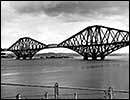
Cantilever bridges are self-supporting during construction. They are often used in situations in which the use of scaffolding or other temporary supports would be difficult. The Forth Bridge, a railway bridge across the Firth of Forth in Queensferry, Scotland, has two main spans of 521 m (1,710 ft) each. The Hâora (Howrah) Bridge in Calcutta (now Kolkata), India, was opened in 1943, with a main span of 457 m (1,500 ft). The Québec Bridge across the St. Lawrence River in Canada has a span of 549 m (1,800 ft).
C Arch Bridges
Arch bridges are characterized by their stability. In an arch, the force of the load is carried outward from the top to the ends of the arch, where abutments keep the arch ends from spreading apart. Arch bridges have been constructed of stone, brick, timber, cast iron, steel, and reinforced concrete.
Steel and concrete arches are particularly well suited for bridging ravines or chasms with steep, solid walls. The New River Gorge Bridge in West Virginia is the longest arch bridge, spanning a gap of 518 m (1,700 ft). Other long arch bridges include the Bayonne Bridge between New York and New Jersey, and the Sydney Harbor Bridge in Australia, with main spans of 504 m (1,652 ft) and 503 m (1,650 ft), respectively.
D Truss Bridges Truss bridges utilize strong, rigid frameworks that support these bridges over a span. Trusses are created by fastening beams together in a triangular configuration. The truss framework distributes the load of the bridge so that each beam shares a portion of the load. Beam, cantilever, and arch bridges may be constructed of trusses. Truss bridges can carry heavy loads and are relatively lightweight. They are also inexpensive to build. The Astoria Bridge over the Columbia River in Oregon has a span of 376 m (1,232 ft).
E Suspension Bridges
Suspension bridges consist of two large, or main, cables that are hung (suspended) from towers. The main cables of a suspension bridge drape over two towers, with the cable ends buried in enormous concrete blocks known as anchorages. The roadway is suspended from smaller vertical cables that hang down from the main cables. In some cases, diagonal cables run from the towers to the roadway and add rigidity to the structure. The main cables support the weight of the bridge and transfer the load to the anchorages and the towers.
Suspension bridges are used for the longest spans. The Brooklyn Bridge, which was the worlds longest suspension bridge at the time of its completion in 1883, crosses the East River in New York City and has a main span of 486 m 31 cm (1,595 ft 6 in). The Akashi Kaikyo Bridge between Honshû and Awaji Island in Japan was completed in 1998, with a span of 1,991 m (6,532 ft). While suspension bridges can span long distances, this design has a serious drawback: It is very flexible, and traffic loading may cause large deflections, or bending, in the bridge roadway. Suspension design is rarely used for railroad bridges, because trains are heavier and can travel faster than highway traffic.
F Cable-Stayed Bridges
Cable-stayed bridges represent a variation of the suspension bridge. Cable-stayed bridges have tall towers like suspension bridges, but in a cable-stayed bridge, the roadway is attached directly to the towers by a series of diagonal cables. A cable-stayed bridge is constructed in much the same way as a suspension bridge is, but without the main cables.
Cable-stayed designs are used for intermediate-length spans. Advantages a cable-stayed bridge has over a standard suspension bridge include speed of construction and lower cost, since anchorages are not necessary. There are no massive cables, as with suspension bridges, making cable repair or replacement simpler. The Pont de Normandie (Normandy Bridge) over the Seine River near La Havre in France opened in 1995, with a span length of 856 m (2,808 ft).
G Movable Bridges
Movable bridges make up a class of bridge in which a portion of the bridge moves up or swings out to provide additional clearance beneath the bridge. Movable bridges are usually found over heavily traveled waterways. The three most common types of movable bridge are the bascule (drawbridge), vertical-lift, and swing bridges. Modern bascule bridges usually have two movable spans that rise upward, opening in the middle. A vertical-lift bridge consists of a rigid deck frame held between two tall towers. The bridge opens by hoisting the entire bridge roadway upward between the towers in an elevator-like fashion. Swing bridges are mounted on a central pier and open by swinging to one side, allowing ships to pass.
Movable bridges are generally constructed over waterways where it is either impractical or too costly to build bridges with high enough clearances for water traffic to pass underneath. Bascule bridges are used for short spans. A bascule bridge over the Black River in Lorain, Ohio, has a length of 102 m (333 ft). Vertical-lift bridges are useful for longer spans, but they must be built so they can be lifted high enough for tall ships to pass underneath. The vertical-lift bridge over Arthur Kill between Staten Island in New York City and New Jersey has a span of 170 m (558 ft) and can be raised 41 m (135 ft) above the water. Swing bridges have the advantage of not limiting the height of passing vessels, but they do restrict the horizontal clearance, or width, of passing ships. The longest swing-bridge span is that of a railroad and highway bridge crossing the Mississippi River at Fort Madison, Iowa. This bridge has a span of 166 m (545 ft).
H Floating Bridges
Floating bridges are formed by fastening together sealed, floating containers called pontoons and placing a roadbed on top of them. A pontoon typically contains many compartments so that if a leak occurs in one compartment, the pontoon will not sink. Some floating bridges are constructed using boats or other floating devices rather than pontoons.
Floating bridges were originally developed and are most widely used as temporary structures for military operations. For everyday use, floating bridges are popular when deep water, bad riverbed conditions, or other conditions make it difficult to construct traditional bridge piers and foundations. A concrete-pontoon bridge carries a highway across Lake Washington, near Seattle, Washington. It consists of 25 floating sections bolted together and anchored in place and a span that can be opened to permit the passage of large ships. The floating section of the bridge is 2.3 km (1.4 mi) long.
I Combination Bridges
Combination bridges include crossings consisting of several types of bridges or both bridges and tunnels. For example, the Chesapeake Bay Bridge-Tunnel in Virginia includes two tunnels that are each 1.6 km (1.0 mi) long along its 28 km (17 mi) length from shore to shore. The Triborough Bridge in New York City is actually a network of bridges connecting the boroughs of Queens, Manhattan, and the Bronx. These bridges meet over Randalls Island. Seven truss spans stretch over Bronx Kills, and three truss spans and a vertical lift extend over the Harlem River. A viaduct and a suspension bridge also make up part of the Triborough Bridge.
III BRIDGE PLANNING AND CONSTRUCTION
New bridges are built either to replace old structures that no longer meet the demands of modern traffic or to cross obstacles on a new transportation route. Old bridges are replaced when repairs cannot be made economically or when traffic becomes too heavy for the old bridge. New transportation routes are built when traffic levels have outgrown the capacity of existing routes or simply to make it faster to get from one busy place to another. Often, new transportation routes are part of government programs to promote regional economic development.
In the United States, state and local transportation agencies determine where new bridges are needed and pay a small portion of the cost. The federal government usually pays for most of the construction expense, using money generated from taxes. Bridges funded by tax dollars are used free of charge. The few bridges for which a toll is charged to drivers for use are funded through the sale of bonds to raise money for construction. The money collected from the toll is used to pay back the bonds. The use of tolls and borrowing to finance bridge construction was more widespread in the past than it is today.
A Design Selection Engineers must consider several factors when designing a bridge. They consider the distance to be crossed and the feature, such as a river, bay, or canyon, to be crossed. Engineers must anticipate the type of traffic and the amount of load the bridge will have to carry and the minimum span and height required for traffic traveling across and under the bridge. Temperature, environmental conditions, and the physical nature of the building site (such as the geometry of the approaches, the strength of the ground, and the depth to firm bedrock) also determine the best bridge design for a particular situation.
Once engineers have the data they need in order to design a bridge, they create a work plan for constructing it. Factors to be considered include availability of materials, equipment, and trained labor; availability of workshop facilities; and local transportation to the site. These factors, in combination with the funding and time available for bridge design and construction, are the major requirements and constraints on design decisions for a particular site.
B Design Decisions There are four basic categories of design decisions: the type of bridge, the materials of which it will be made, the type of foundations that will support the structure, and the construction method to be used. Typically, several feasible choices exist in each category, and each option is evaluated in terms of convenience, appearance, endurance, and cost. Bridges must be convenient to build, use, and maintain. Appearance is important in gaining public approval, which is particularly critical for taxpayer-funded projects. Bridges must be designed to endure, as most structures can be expected to provide service for at least 50 to 100 years. Durability of materials and maintenance requirements are important considerations, as the true cost of a bridge is not simply the initial construction expense but the total cost of constructing and maintaining the structure throughout its service life. Good designs minimize total cost.
B1 Bridge Type The bridge type (such as beam, arch, truss, and others) depends largely on the required dimensions for the bridge and the type of traffic to be carried. The required length and clearances needed by traffic are major considerations in bridge design. Many bridges are long enough to require several intermediate supports, or piers. The location of piers is usually a crucial factor, whether in water or on land.
B2 Materials Materials historically used for bridge building include rope and other fibers, wood, stone and masonry, iron, steel, and concrete. Fiber, timber, stone, and masonry are still used occasionally, but steel and concrete are the materials used for most modern bridge building. Fiber rope is occasionally used for short pedestrian bridges. Timber is perceived as a rustic material and is sometimes used in public parks, on private property, or in other situations in which a natural or historic appearance is desirable. The strength and durability of timber are quite limited compared to those of steel and concrete. Therefore, timber is suitable only for short spans that carry minimal traffic loads. Stone and masonry are sometimes used as facing materials on concrete and steel bridges, if appearance is important enough to justify the additional expense.
When deciding between steel and concrete, designers evaluate the tradeoffs among weight, strength, and expense to determine which material is best for a particular bridge. Concrete is heavier than steel, but steel is much stronger. The major advantages of concrete are that it is considerably cheaper than steel and can be formed into a greater variety of shapes. For short bridges, the weight of material is not an important concern, and so concrete is an economical choice. However, as span increases, the weight of the structure grows substantially, and greater strength is needed to support the overall structure. Steel tends to be preferred for large bridges because less material has to be handled and supported during the construction process.
The distinction between steel and concrete is not absolute, as most steel bridges have concrete decks, and all concrete is reinforced with steel to provide greater tensile strength (resistance to pulling). Reinforced concrete is made by pouring concrete mix over steel bars or mesh. The concrete and metal bond as the mix hardens, producing a material in which the high tensile strength of steel is combined with the great compressive strength (ability to resist pushing or squeezing) of concrete. An alternative method of reinforcing concrete is prestressing. Prestressed concrete is made by pouring concrete over stretched and anchored steel strands. After the concrete has set, the anchors are released. As the steel tries to return to its original length, it compresses the concrete, resulting in a relatively lightweight, extremely strong material.
B3 Foundations All bridge piers rest on foundations that transfer loads from the bridge structure into the ground. The foundations support the bridge, and their design is critical. Difficult conditions, such as deep water or soft ground, can make foundation construction complicated and expensive. In such circumstances designers may choose to decrease the number of piers by increasing span length. Of course, greater span lengths often require a more expensive bridge type, and therefore the tradeoffs must be evaluated carefully.
If the ground is very strong at a bridge site, a foundation is formed by pouring a simple concrete mat beneath each of the piers. If the soil is weak, it may be excavated down to bedrock, and the piers can then be built directly on the solid rock. Alternatively, a group of vertical posts, or piles, can be driven through the soil to bedrock, and piers can be built on top of the piles.
B4 Construction Methods Bridges are erected using a variety of construction methods. Some techniques are associated with a particular bridge type, and care must be taken not to select a design that requires construction methods unsuitable for the site. Concrete and steel bridges are generally built using similar techniques, although concrete bridges are built in shorter sections than are steel bridges because of the greater weight of the material.
One of the simplest construction methods for bridges is to assemble a span away from the bridge site and then transport it to the site. The span can then be lifted into position as one piece. This method is most often suitable for small truss bridges or for the suspended span of a cantilever truss. Another approach is to use falsework, or temporary scaffolding, to support the incomplete parts of a bridge before they are joined and able to support themselves. The use of falsework is not always possible, owing to strong river currents, interference with river traffic, or great distances to the ground. If falsework is impractical, bridges can be constructed by the cantilever method. With this technique, a bridge is built piece by piece, with the entire structure supported from the section previously completed. Thus, the structure is self-supported throughout the entire construction process. The use of cantilever construction methods saves material and therefore expense, but it is very complex, as great care must be taken not to unbalance the structure during construction. Most arch bridges, and of course cantilever bridges, are built using cantilever methods.
The large towers and cable anchorages of suspension bridges are built without the use of falsework, and then the suspension cables are spun. Many individual wires are draped over the towers and are then squeezed together into a circular shape and clamped at intervals to create a main cable. Suspension wires are dropped from the cables to support the roadway, and the roadway is completed.
For all bridge types, underwater foundations require unique construction methods. Builders use cofferdams and caissons to obtain access to ground that is normally under water. A cofferdam is a temporary watertight enclosure constructed on the spot where a pier is to be built. A cofferdam usually consists of sheets of steel driven into the ground to create a walled chamber. The cofferdam is then pumped dry to expose the riverbed. Soil can be excavated to bedrock, or piles can be driven to create the pier foundation. The cofferdam is removed after the foundation and pier are constructed. A caisson is a large cylinder or box chamber that is sunk into the riverbed. The excavation and foundation work takes place within the submerged caisson. Some caissons are removed after construction, while others are left in place, filled with concrete, and used as part of a permanent foundation.
C Safety
In bridge design, engineers strive to plan an economical structure that will safely transmit loads to the ground without collapsing or deforming excessively. Since it is difficult to predict the exact loading and circumstances that a bridge must withstand, all bridge designs include a substantial margin of safety. Design standards vary throughout the world, but all aim at ensuring that new bridges will provide many years of service and will maintain an adequate margin of safety against failure. Of course, the safety of a structure when it is first erected does not ensure that it will remain safe for all time. All structures require both periodic inspection and proper maintenance to keep them safe. Notable bridge failures include the collapse of the Firth of Tay Bridge in Scotland in 1879, the collapse of the Québec Bridge in Canada while under construction in 1907, and the collapse of the Tacoma Narrows Bridge, nicknamed Galloping Gertie, in Washington State in 1940.
IV HISTORY The different sizes and shapes of bridges encountered today reflect thousands of years of progress in engineering, technology, and building materials.
A Early and Medieval Bridges
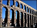
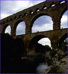
In ancient times, builders would throw a log across a stream or use two vines or ropes (the upper for a handhold and the lower for a foothold) to create a crossing. The earliest rudimentary arches (built from 4000 to 2000 BC) consisted of stones balanced on top of one another. The ancient Romans perfected stone arch design and were the first to build large-scale bridges, many of which still stand today. The largest remaining ancient Roman aqueduct, the Pont du Gard in southern France, is 270 m (886 ft) long and consists of three tiers of semicircular stone arches. The Romans built the Pont du Gard in the late 1st century BC or the early 1st century AD. The aqueduct stands approximately 47 m (155 ft) tall, and the longest arch spans 24 m (80 ft).
The ancient Chinese also built many notable bridges. In the 7th century AD, bridge designer Li Chun built the Anji Bridge south of Beijing using a stone arch built of massive limestone wedges reinforced with iron. The innovative main arch of the Anji curves in a shallow arc or segment of a circle, rather than the half circle preferred by Roman engineers at the time. The Anji Bridge, which spans 37 m (121 ft), predates any comparable development in Europe by several hundred years.
From ancient times through the 16th century, designers made few engineering advances. Masonry arch construction remained the premier choice for bridge design. In the Middle Ages in Europe, religious orders administered bridge construction. Considered pious works, bridges often had chapels and were decorated with effigies of saints. Inhabited bridges were developed during the Renaissance. These bridges were exemplified by the Ponte Vecchio, 100 m (330 ft) long, in Florence, Italy, designed by Taddeo Gaddi in 1345; and by the Rialto Bridge, 27 m (89 ft) long, in Venice, Italy, designed by Antonio da Ponte in 1591. Shops were built directly on the roadway of these bridges, and rents were used to finance new public works.
B Iron and Steel Bridges
The widespread use of iron in the 18th century and the introduction of the steam locomotive in the 19th century encouraged rapid innovation in bridge design. Engineers made more advances in the first half of the 19th century than they had in the previous 1,800 years. As the railroad industry developed, bridges rapidly increased in height, span, strength, and numbers. Iron was plentiful, cheap, much stronger than wood, and more flexible than stone. The Ironbridge at Coalbrookdale, England, completed in 1779, was the first major structure to be constructed entirely of iron. Designed by Abraham Darby III and Thomas Pritchard, the arched structure spans about 30 m (about 100 ft). Scottish engineer Thomas Telford used wrought iron and limestone to design the Menai Suspension Bridge in Wales in 1826. This bridge was the worlds first major suspension bridge. It spanned 176 m (579 ft). During the first half of the 19th century, iron became the premier building material. In addition, truss designs were developed to provide the additional strength needed to bear the massive weight of railroad trains.
The major disadvantage of iron, namely, low tensile strength, was overcome in the mid-1850s, when the Bessemer process of making steel (an alloy of iron and carbon) was developed. The first major structure built entirely of steel was the cantilevered Forth Bridge in Scotland, completed in 1890. Its two record-setting spans of 521 m (1,710 ft) were the longest in existence until 1917. The arched Eads Bridge over the Mississippi River at St. Louis, Missouri, designed by James Eads and completed in 1874, was the first steel bridge in the United States. The Eads Bridge has three main spans. The center span is 160 m (520 ft) long, and the spans on either side are each 153 m (502 ft) in length. At the time the Eads Bridge was built, it was the longest structure in the United States. By 1890 the strength and lightness of steel had made it the material of choice for bridge building.
C Suspension Bridges The Roebling family pioneered the use of steel in suspension bridges. John Augustus Roebling, a German-born engineer who emigrated to the United States in 1831, is considered the father of modern suspension-bridge design. His major contribution was the development of construction techniques to spin wire cables. He was the first to use cables and stiffening trusses in suspension bridges. Roebling designed the Cincinnati Bridge, over the Ohio River at Cincinnati, Ohio. It was built by his son Washington Roebling in 1866. The Cincinnati Bridge has a span of 322 m (1,057 ft).
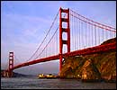
John and Washington Roebling also designed and built the Brooklyn Bridge, which was the worlds longest suspension bridge at the time of its completion in 1883, having a main span of 486 m 31 cm (1,595 ft 6 in). The completion of the Brooklyn Bridge marked the beginning of an 80-year period of large-scale suspension-bridge design in the United States. That period ended in 1964 with the completion of the Verrazano-Narrows Bridge in New York City. The Golden Gate Bridge in San Francisco, California, is perhaps the best-known landmark of this remarkable era in bridge building (see Golden Gate). Completed in 1937, the Golden Gate Bridge has a main span of 1,280 m (4,200 ft).
D Introduction of Concrete
The introduction of concrete as a building material represented a major chapter in the history of bridge building. Although the ancient Romans had used concrete, the knowledge of this material virtually disappeared during the Middle Ages and was not rediscovered until the late 18th century. The first modern concrete bridge was a solid concrete bridge, 12 m (39 ft) long, built over the Garonne Canal at Grisoles, France, in 1840.
All early concrete bridges used arched designs by necessity because concrete has great compressive strength but is very weak in tension. Until the invention of metal reinforcement, which adds strength in tension, the arch was the only feasible shape for structures made entirely of concrete. Reinforced concrete emerged simultaneously in Germany, the United States, England, and France between 1870 and 1900. Swiss engineer Robert Maillart became a celebrated designer of reinforced-concrete bridges in the first half of the 20th century, producing extremely innovative designs based on the unique engineering properties of reinforced concrete. The last half of the 20th century saw the construction of major reinforced-concrete structures, such as the Lake Maracaibo Bridge in Venezuela, designed by Italian engineer Riccardo Morandi. This prestressed-concrete cable-stayed bridge is 8 km (5 mi) long.
E Recent Designs
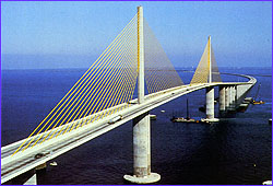
The first modern cable-stayed bridge featured a span of 183 m (600 ft). German engineers constructed this bridge in Sweden in 1956. Thereafter, Germany led the field in developing this type of bridge. Cable-stayed bridges can be constructed in an infinite variety of shapes and are one of the most popular long-span bridge designs. Notable examples include the Severn II Bridge in Bristol, England, completed in 1996 with a span of 456 m (1,496 ft), and the Sunshine Skyway Bridge in Tampa, Florida, completed in 1987 with a span of 366 m (1,200 ft).
At the end of the 20th century, construction was under way on a number of monumental bridges, most notably in Northern Europe and in Asia. Engineers are combining aspects of both suspension and cable-stayed bridges into new bridge designs that will someday span once-impossible distances of more than 3,000 m (10,000 ft). At the same time, researchers are investigating new methods of preserving and renewing bridges, so that existing structures will last longer and provide greater service and fewer new structures will have to be built in the future.
Contributed By:
B. Cameron Schultz
Dimitri A. Grivas
1
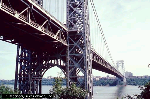
George Washington Bridge
The George Washington Bridge crosses the Hudson River to link New York and New Jersey. It is a suspension bridge, with the roadway suspended from two towers by cables. It has two levels for motor-vehicle traffic.
E.R. Degginger/Bruce Coleman, Inc.2
golden_gate_bridge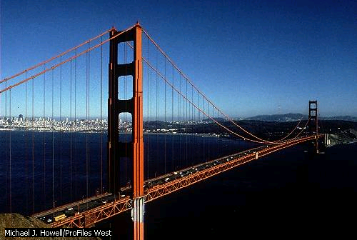
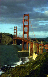
Golden Gate Bridge, San Francisco
The Golden Gate Bridge links the city of San Francisco with Marin County to the north. The suspension bridge was opened in 1937 and since then has been one of the principal landmarks of both San Francisco and California.
Michael J. Howell/ProFiles West3
verrazano_narrows_bridge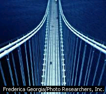
Verrazano-Narrows Bridge
An overview of the Verrazano-Narrows steel suspension bridge reveals the structure and cable system that allows it to support weight over an extended span. The bridge links Brooklyn and Staten Island at the entrance of New York Harbor, crossing 1,298 m (4,260 ft) of water. Cable systems often rise hundreds of meters above the roadway; at the peak of its towers the Verrazano-Narrows is 210 m (690 ft) tall. More than 135,000 metric tons (150,000 U.S. tons) of steel were used in the bridge, which cost $325 million to build.
Frederica Georgia/Photo Researchers, Inc.4
iron_rail_bridge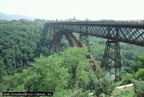
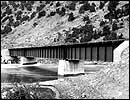
Iron Rail Bridge
An early iron arch bridge supporting a railway spans the Adda River in northern Italy. The arch makes use of truss framework to help support the bridge.
Danilo Donadoni/Bruce Coleman, Inc.5
masonry_arch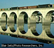
Masonry Arch Bridge
This railroad bridge near Harrisburg, Pennsylvania, has cut stones arranged in a semicircular arch construction. Masonry arch bridges have largely been replaced by steel and concrete arch bridges because masonry bridges are more expensive to build.
Blair Seitz/Photo Researchers, Inc.6
oldest_bridge_australia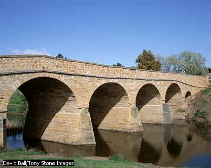
Oldest Bridge in Australia
In 1823 convicts built the stone bridge pictured here, near the town of Richmond, in Tasmania, Australia. The bridge, the oldest in Australia, connected the city of Hobart with the penal colony of Port Arthur.
David Ball/Tony Stone Images7
clifton_bridge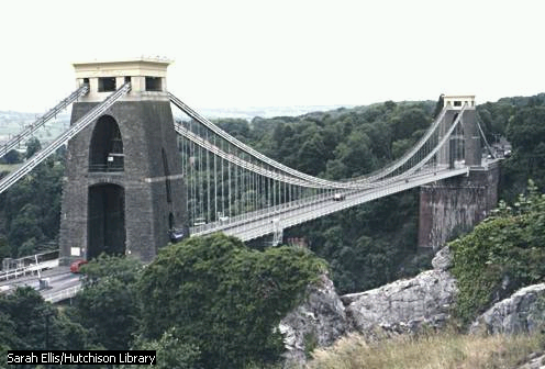
Clifton Bridge
Suspension bridges, like the Clifton Suspension Bridge in Bristol, England, are commonly used in areas where building a bridge with mid-span supports would be either extremely difficult or overly expensive. The span hangs from two enormous main cables, eliminating the need to bolster the span from underneath. In turn, the main cables place their load on the towers at each end of the bridge, and on the points where the cables are attached to the ground beyond each of the towers.
Sarah Ellis/Hutchison Library8
brooklyn_bridge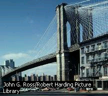
Brooklyn Bridge
Designed by German-American John Roebling, the Brooklyn Bridge was the longest suspension bridge in the world when it opened on May 24, 1883. The bridge spans the East River in New York City and connects the densely populated boroughs of Brooklyn and Manhattan.
John G. Ross/Robert Harding Picture Library9
mackinac_bridge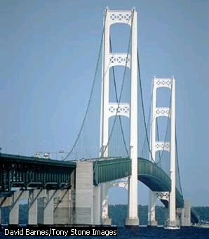
Mackinac Bridge
The Mackinac Bridge in northern Michigan is one of the longest suspension bridges in the world, with a total span of more than 2.5 km (more than 1.5 mi). It connects Michigans Upper Peninsula (between Lake Superior and Lake Michigan) and Lower Peninsula (between Lake Michigan and Lake Huron).
David Barnes/Tony Stone Images10
yokohama_bay_bridge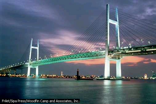
Yokohama Bay Bridge
The 860-meter (2,822-foot) Yokohama Bay Bridge crosses part of Tokyo Bay. The cable-stayed bridge reflects the modern character of the city of Yokohama, which was almost completely rebuilt after an earthquake caused widespread destruction in 1923. The city is now an industrial center and leading seaport for Japan.
Frilet/Sipa Press/Woodfin Camp and Associates, Inc.11
london_tower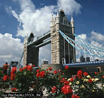
London Tower Bridge
The 244-m (800-ft) London Tower Bridge spans the Thames River in London. It was the only movable bridge crossing the Thames when it was completed in 1894. Sir Horace Jones designed the bridge, and Sir John Wolfe Barry built it.
Guy Marche/ALLSTOCK, INC.12
vertical_lift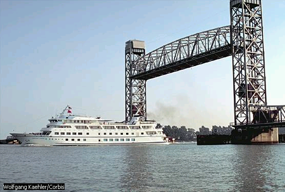
Vertical-lift Bridge
A vertical-lift bridge raises the entire span along two towers to allow ships to pass below. A vertical-lift bridge can span a greater distance than a bascule bridge, but the fixed height of a vertical-lift bridge may restrict the passage of very tall ships.
Wolfgang Kaehler/Corbis13
newcastl_ upon_tyne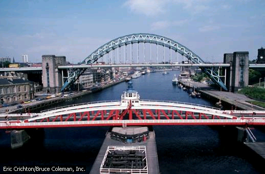
Bridges in Newcastle upon Tyne
The 1876 swing bridge, foreground, and the modern Tyne Bridge span the Tyne River in the ancient city of Newcastle upon Tyne in England. The city flourished as an exporter of coal from the Middle Ages until the later 20th century.
Eric Crichton/Bruce Coleman, Inc.14
bascule_bridge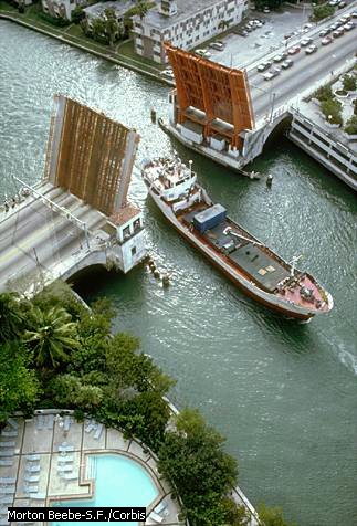
Bascule Bridge
A bascule bridge on the Miami River in Florida is open to let a ship pass. Bascule bridges are useful for spanning short distances over busy waterways, and they allow ships of any height to pass underneath.
Morton Beebe-S.F./Corbis15
evergreen_point_floating_bridge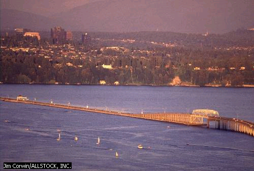
Evergreen Point Floating Bridge
The Evergreen Point floating bridge spans Lake Washington near Seattle, Washington. Built on concrete pontoons, the floating span stretches for 2.3 km (1.4 mi), and supports a major flow of freeway traffic. The bridge consists of 25 individual sections, one of which is a telescoping floating span. The telescoping section can be opened to allow the passage of large ships, or to relieve stress on the bridge during high windstorms.
Jim Corwin/ALLSTOCK, INC.16
pontoon_floating_bridge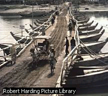
Floating Bridge
The simple pontoon floating bridge over the Kâbul River, Pakistan, is supported by flat-bottomed boats rather than fixed piers. Pontoon bridges may also be supported by other types of floats or metal cylinders.
Robert Harding Picture Library17
chesapeake_bay_bridge_tunnel
Chesapeake Bay Bridge-Tunnel
Chesapeake Bay features a piece of construction that may startle unprepared travelers. The 28.2 km (17.5 mi) crossing between Norfolk and Cape Charles, Virginia, begins as a bridge, but disappears into the water midway. A combination structure, the Chesapeake Bay Bridge-Tunnel combines two bridges with two tunnels that pass under major shipping channels.
Chesapeake Bay Bridge and Tunnel District18
concrete_bridge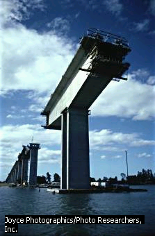
Concrete Bridge
Modern bridge construction for the Gateway Bridge over the Brisbane River in Australia uses lightweight and durable concrete reinforced with steel bars or mesh. Concrete is made from three components: an aggregate material such as sand or gravel, water, and the binding agent, portland cement.
Joyce Photographics/Photo Researchers, Inc.19
ponte_vecchio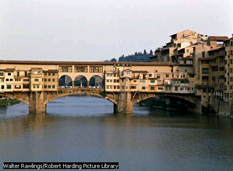
Ponte Vecchio, Florence, Italy
Many of the older bridges in Florence were destroyed during World War II; however, the Ponte Vecchio (Old Bridge), built in 1345 and shown here, survived. Goldsmith and jewelry shops line the bridge.
Walter Rawlings/Robert Harding Picture Library20
ironbridge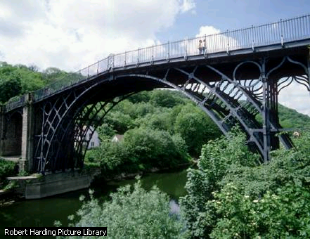
Ironbridge, Telford, England
Ironbridge, which crosses the River Severn in Telford, Shropshire, in western England, was completed in 1779. The first large-scale structure made of cast iron, the bridge was considered a remarkable feat of engineering at the time of its construction.
Robert Harding Picture Library21
paul_sauer_bridge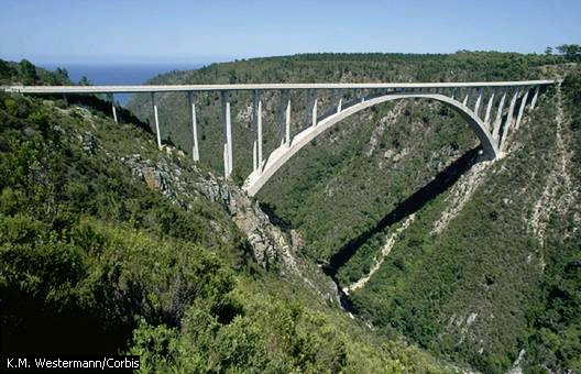
Paul Sauer Bridge, South Africa
The concrete arch of the Paul Sauer Bridge spans the Storms River in South Africa, on the road between Cape Town and Port Elizabeth. An arch bridge transfers the weight of the bridge down along the arch to the abutments where, in this example, the arch meets the canyon walls.
K.M. Westermann/Corbis22
normandy_bridge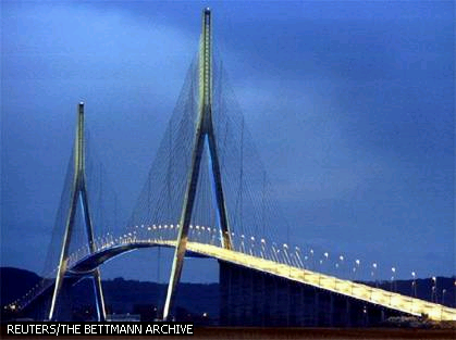
Normandy Bridge
Normandy Bridge near Le Havre, France, is one of the worlds longest cable-stayed suspension bridges, with a main span of 856 m (2808 ft). The bridge opened to traffic in January 1995. Unlike conventional suspension bridges, which use two massive cables, cable-stayed bridges employ numerous smaller cables attached to two large towers or pylons.
REUTERS/THE BETTMANN ARCHIVE23
BUILDING BIG: Forces Lab |
 |
 |
 |
 |
 |
 |
 |
 |
 | |
     |
 | ||
 | |||
     |
 | ||
|
There is also a text version of this lab. These Labs require the most recent version of the Flash plug-in. You can download Flash from the Macromedia web site for free. If you are having trouble with Flash, please take a look at our Help page. |
Day 7: Arch Bridges
Warm Up: Can a material become stronger just by bending it?
Activity:
Homework:Begin Planning your popsicle stick bridge design.You may visit this web site: http://bellnet.tamu.edu/res_grid/trussb/designs.htm for help
Internet Resources:
Trusses: http://bellnet.tamu.edu/res_grid/trussb/designs.htm to see many more examples of truss designs and actual pictures of truss bridges.
Arches: Pictures and descriptions of how arches work: http://207.99.133.13/science/7th%20Grade/bridges/arch_lessons/arch_lessons.htm
Test your bridges mass by building a balance:
 ..........
View Movie of Bridge Being Broken
Points = 300: 100 for completing a bridge, 200 according to strength
|
|
|
|
|
|
|
|
|
|
|
|
|
|
|
|
|
|
|
|
|
|
|
|
|
|
|
|
|
|
|
|
|
|
|
|
|
|
|
|
|
|
|
|
|
|
|
|
|
|
|
|
 |
 |
 |
 |
 |
 |
 |
 |
  |
     |
 |
There are more than half a million bridges in the United States, and you rely on them every day to cross obstacles like streams, valleys, and railroad tracks. But do you know how they work? Or why some bridges are curved while others are straight? Engineers must consider many things -- like the distance to be spanned and the types of materials available -- before determining the size, shape, and overall look of a bridge. Since ancient times, engineers have designed three major types of bridges to withstand all forces of nature.
 The beam
bridge... The beam
bridge...consists of a horizontal beam supported at each end by piers. The weight of the beam pushes straight down on the piers. The farther apart its piers, the weaker the beam becomes. This is why beam bridges rarely span more than 250 feet. Sneak a peek at the forces that act on beam bridges! Check out other types of beam bridges!

The truss bridge... consists of an assembly of triangles. Truss bridges are commonly made from a series of straight, steel bars. The Firth of Forth Bridge in Scotland is a cantilever bridge, a complex version of the truss bridge. Rigid arms extend from both sides of two piers. Diagonal steel tubes, projecting from the top and bottom of each pier, hold the arms in place. The arms that project toward the middle are only supported on one side, like really strong diving boards. These "diving boards," called cantilever arms, support a third, central span. Check out the forces that act on truss bridges!

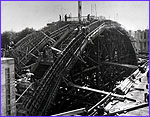
The arch bridge... has great natural strength. Thousands of years ago, Romans built arches out of stone. Today, most arch bridges are made of steel or concrete, and they can span up to 800 feet. Catch a glimpse of the forces that act on arch bridges! Check out how arch bridges are built!

The suspension bridge...
can span 2,000 to 7,000 feet -- way farther than any other type of bridge! Most suspension bridges have a truss system beneath the roadway to resist bending and twisting. See how forces act on suspension bridges! Check out another type of suspension bridge! Now that you've mastered the bridge basics, test your bridge-building skills in the Bridge Challenge! |
 | ||||||||||
 | |||||||||||||
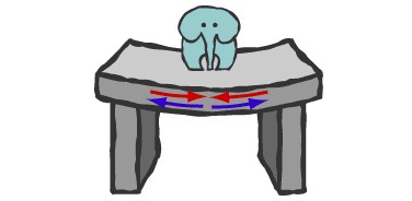
Beam Bridge: Forces
When something pushes
down on the beam, the beam bends. Its top edge is pushed together, and its bottom
edge is pulled apart.
 |
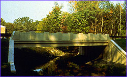
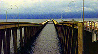
| Continuous span beam bridge |

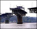 |
| Swing bridge: George P. Coleman Bridge |

Truss Bridge: Forces
Every bar in this cantilever
bridge experiences either a pushing or pulling force.
The bars rarely bend. This is why
cantilever bridges can span farther than beam bridges.
29


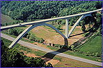
Arch Bridge: Forces
The arch is squeezed
together, and this squeezing force is carried
outward along the curve to the supports at each end. The supports, called
abutments, push back on the arch and prevent the ends of the arch from spreading
apart.
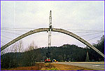
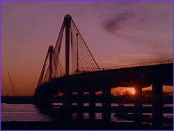
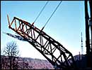 |
| Arch bridge being constructed with cables |

Suspension Bridge: Forces
In all suspension
bridges, the roadway hangs from massive steel
cables, which are
draped over two towers and secured
into solid concrete blocks,
called anchorages, on both ends of the bridge. The cars push down on the
roadway, but because the roadway is suspended, the cables transfer the load into compression
in the two towers. The two towers support most of the bridge's weight.
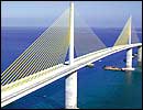 |
| Cable-stayed bridge: Sunshine Skyway Bridge |

 34
34
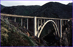 Bixby Creek Bridge, Monterey, CA |
 Cut a strip of cardboard that's about one inch by 11
inches. Gently bend the strip so that it has a curve. Position the cardboard on
a table so that it resembles an arch. Press down on the center of the arch. What
happens to the ends of the cardboard?
Cut a strip of cardboard that's about one inch by 11
inches. Gently bend the strip so that it has a curve. Position the cardboard on
a table so that it resembles an arch. Press down on the center of the arch. What
happens to the ends of the cardboard?
 Next, place a stack of books
at each end of the arch. Press again. Now what happens? Notice how the stacks of
books act as abutments, keeping the ends of the arch from spreading apart.
Next, place a stack of books
at each end of the arch. Press again. Now what happens? Notice how the stacks of
books act as abutments, keeping the ends of the arch from spreading apart.
When supporting its own weight and the weight of crossing traffic, every part of the arch is under compression. For this reason, arch bridges must be made of materials that are strong under compression.
 |
 |
 |
 |
 |
(back to intro)
(next
bridge description: beam bridge)
35
 |
In its most basic form, a beam bridge consists of a horizontal beam that is supported at each end by piers. The weight of the beam pushes straight down on the piers.
The beam itself must be strong so that it doesn't bend under its own weight
and the added weight of crossing traffic. When a load pushes down on the beam,
the beam's top edge is pushed together (compression) while the bottom edge is
stretched (tension).
Try It!
 Take a flat eraser or a small
sponge and slice a shallow notch across the top and bottom. Create a beam bridge
by supporting each end of the eraser (or sponge) with a stack of books. Press
down on the center of the bridge. What happens to the top and bottom notches?
Notice how the top notch squeezes together in compression, while the bottom
notch spreads apart under tension.
Take a flat eraser or a small
sponge and slice a shallow notch across the top and bottom. Create a beam bridge
by supporting each end of the eraser (or sponge) with a stack of books. Press
down on the center of the bridge. What happens to the top and bottom notches?
Notice how the top notch squeezes together in compression, while the bottom
notch spreads apart under tension.
Pre-stressed concrete is an ideal material for beam bridge construction; the concrete withstands the forces of compression well and the steel rods imbedded within resist the forces of tension. Pre-stressed concrete also tends to be one of the least expensive materials in construction. But even the best materials can't compensate for the beam bridge's biggest limitation: its length.
The farther apart its supports, the weaker a beam bridge gets. As a result, beam bridges rarely span more than 250 feet. This doesn't mean beam bridges aren't used to cross great distances -- it only means that they must be daisy-chained together, creating what's known in the bridge world as a "continuous span."
 |
(back to intro)
(next
bridge description: suspension bridge)
36
 Golden Gate Bridge, San Francisco, CA |
 |
Try It!
 Tie two loops of string around the
tops of two hard cover books of similar size. Tie a third piece of string to
each loop so that it hangs loosely between the books. Press down on the center
string. What happens?
Tie two loops of string around the
tops of two hard cover books of similar size. Tie a third piece of string to
each loop so that it hangs loosely between the books. Press down on the center
string. What happens?
 Next, stand two books
about 10 inches apart. Put a stack of heavy books on one end of string to secure
it to the table. Then pass the string over each book (letting some string hang
loosely between the books). Place a second stack of books on the other end of
the string. Press again on the center of the string. What happens? Notice how
the anchorages (stacks of books) help to stabilize the bridge.
Next, stand two books
about 10 inches apart. Put a stack of heavy books on one end of string to secure
it to the table. Then pass the string over each book (letting some string hang
loosely between the books). Place a second stack of books on the other end of
the string. Press again on the center of the string. What happens? Notice how
the anchorages (stacks of books) help to stabilize the bridge.
 |
 |

Tacoma Narrows |

Tacoma Narrows |
| Vivo: isdn | 28.8 RealVideo: isdn | 28.8 QuickTime: (0.6MB) AVI: (0.6MB) |
Vivo: isdn | 28.8 RealVideo: isdn | 28.8 QuickTime: (0.4MB) AVI: (0.4MB) |
You'll need one of three (free) software plugins -- Vivo, RealPlayer, or QuickTime to be able to view the video clips of the Tacoma Narrows bridge. If you already have the software, choose an appropriate connection speed (Vivo, RealVideo) or the file size (QuickTime, AVI) to view a clip.At the time it opened for traffic in 1940, the Tacoma Narrows Bridge was the third longest suspension bridge in the world. It was promptly nicknamed "Galloping Gertie," due to its behavior in wind. Not only did the deck sway sideways, but vertical undulations also appeared in quite moderate winds. Drivers of cars reported that vehicles ahead of them would completely disappear and reappear from view several times as they crossed the bridge. Attempts were made to stabilize the structure with cables and hydraulic buffers, but they were unsuccessful. On November 7, 1940, only four months after it opened, the Tacoma Narrows Bridge collapsed in a wind of 42 mph -- even though the structure was designed to withstand winds of up to 120 mph.
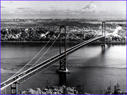 |
Today, wind tunnel testing of bridge designs is mandatory. As for the Tacoma Narrows bridge, reconstruction began in 1949. The new bridge is wider, has deep stiffening trusses under the roadway and even sports a slender gap down the middle -- all to dampen the effect of the wind.
(back to intro)
(next
bridge description: cable-stayed)
37
 Clark Bridge, Alton, IL |
The cables can be attached to the roadway in a variety of ways. In a radial pattern, cables extend from several points on the road to a single point at the top of the tower. In a parallel pattern, cables are attached at different heights along the tower, running parallel to one other.
 |
 |
Stand up and hold your arms out horizontally at each side. Imagine that your arms are a bridge, and your head is a tower in the middle. In this position, your muscles are holding up your arms.
Try making cable-stayeds to support your arms. Take a piece of rope (about five feet long), and have a partner tie each end of the rope to each of your elbows. Then lay the middle of the rope on top of your head. The rope acts as a cable-stayed and holds your elbows up.
 Have your partner tie a
second piece of rope (about 6 feet long) to each wrist. Lay the second rope over
your head. You now have two cable-stayeds. Where do you feel a pushing force, or
compression? Notice how the cable-stayeds transfer the load of the bridge (your
arms) to the tower (your head).
Have your partner tie a
second piece of rope (about 6 feet long) to each wrist. Lay the second rope over
your head. You now have two cable-stayeds. Where do you feel a pushing force, or
compression? Notice how the cable-stayeds transfer the load of the bridge (your
arms) to the tower (your head).
Even though cable-stayed bridges look futuristic, the idea for them goes back a long way. The first known sketch of a cable-stayed bridge appears in a book called Machinae Novae published in 1595, but it wasn't until this century that engineers began to use them. In post-World War II Europe, where steel was scarce, the design was perfect for rebuilding bombed out bridges that still had standing foundations. Cable stay bridges have begun to be erected in the United States only recently, but the response has been passionate.
For medium length spans (those between 500 and 2,800 feet), cable-stayeds are fast becoming the bridge of choice. Compared to suspension bridges, cable-stayeds require less cable, can be constructed out of identical pre-cast concrete sections, and are faster to build. The result is a cost-effective bridge that is undeniably beautiful.
 |


| 1. | understand that ratios are used to create scale models of buildings and structures; |
| 2. | understand the principles of ratio and apply these principles in the solution of problems; and |
| 3. | understand how to calculate scale using ratio. |


 |
 |
 |
 |
 |
 |
 |
 |
 |
 |
 |
 | ||||||
  |
 |
 | ||||||
 |
 |
 Materials Procedures Adaptations Discussion Questions Extensions  |
 Evaluation Suggested Readings Background Information  |
 Vocabulary Academic Standards Credit |
 |
 | ||
 | ||||||||
 |
 |
 |
 |
 |
 | |||
 |
 |
 |
Printable version of the complete lesson plan, including activity sheets. You need the free Adobe Acrobat Reader plugin. |  |
 | |||
 |
 |
 |
 |
 |
 | |||
 | ||||||||


| | 0.25-inch graph paper |
| | map(s) of the United States |
| | pencils |
| | ruler (metric or inches) |
| | tape measure |
| | Take-Home Activity Sheet: Home Measurements |

 | |||||
 |
 |
 |
 |
 |
 |
 |
 |
| Use our Teaching Tools to create custom worksheets, puzzles and quizzes about this topic. |  |
 |
 |
 |
 |
 |
 |
 |
 |
 |
| Discovery Channel School video: Measurement &
Scale. |
 |
 |
 |
 |
 |
 |
 |
 |
 | |||||
 |
 |
 |
 |
 |
 |


| 1. | Begin by introducing the concept of scale. Write the word scale on the board and brainstorm examples of where scales are found and what they measure. For example, we use scales to measure the weight of an object, the temperature of air, the length of an object, and so on. | ||||||
| 2. | Show students a map of the United States and point out the scale in the map key. Remind them that this map is a smaller, scaled-down representation of the United States, not an actual representation. Explain that sometimes we shrink objects or make them larger so they are easier to work with. The map is a scale model of an object that is too large to represent on paper. Other scale models represent objects that are too small, such as a diagram of an atom or a magnified view of a computer chip. Review the scale on the map. For example, the scale may say that 1 inch is equal to 50 miles. Explain that a scale is a ratio used to determine the size of a model of a real object. In this case, the map of the United States is the model. | ||||||
| 3. | A ratio is a relationship between two objects in quantity, size, or amount. For example, four quarters are in a dollar, so the ratio of quarters to dollar is 4 to 1. In other words, a quarter is one-fourth the value of a dollar. Have students think of other examples of how money can be turned into a scale, such as dimes to dollars (10:1 or 1:10) or pennies to dollars (100:1 or 1:100). | ||||||
| 4. | Illustrate how to draw an object to scale. Use a ruler to draw a square on the board with sides that equal 10 inches in length. Ask students how they might use this square to draw another that is half its size. Explain that an object is not simply cut in half when it is scaled down. The whole object is shrunk proportionally, meaning that it doesnt change shape but is reduced to a smaller size. For example, if you could scale a carrot to half its size, you wouldnt simply cut the carrot in half. All parts of the carrot need to shrink equally in size. | ||||||
| 5. | Now measure and draw a second square with 5-inch sides. Explain that when an object is scaled down, the length of its sides must be reduced by the same amount. Compare the corresponding sides of the two squares. The ratio of the small square to the larger is 5:10. Explain that a ratio can be expressed in three ways: 5:10, 5 to 10, or 5/10, which is a fraction that reduces to 1/2. | ||||||
| 6. | Remind students that the perimeter of an object is the sum of the length of its sides. So if an object has been scaled down proportionally, the perimeter of the object will scale down by the same ratio. For example, the perimeter of the smaller square is 20, or 5 × 4, which is half the perimeter of the larger square, which is 40, or 10 × 4. | ||||||
| 7. | Explain that students will use ratio to make a scale drawing of the classroom floor plan. First invite students to brainstorm a list of the kinds of people who might use scale drawings. (Examples include architects, construction workers, and cartographers.) | ||||||
| 8. | Divide students into teams of four. Explain that each team will measure the surface areas of objects in the classroomthe desks, tables, closets, and so on. The class may choose to use either metric or English measurements. Explain to students that their floor plan will show objects in the classroom as seen from above. Each group should have access to a tape measure, pencils, and paper to record their measurements. | ||||||
| 9. | Construct a class data table on the board with three columns labeled object, measurement, and scaled measurement. Students should copy this table in their notebooks and fill in the answers as they measure the objects. | ||||||
| 10. | Once teams have recorded all their data, they will decide on the scale of their floor plan. Distribute graph paper. With the class, discuss the proportions that would allow students to draw the entire room on one sheet of 8.5" × 11" graph paper. (For example, if the longest wall in the classroom is 16 feet long, then a scale of 1" = 1 will not work. But 0.5" = 1 will work perfectly.) | ||||||
| 11. | Use the agreed-upon ratio to create the proportion for
your classroom. Then have groups convert their measurements into scaled
equivalents. For example, if a desktop measures 2 feet in width and the scale is
0.5" = 1, use the following equation to figure out how large the scaled drawing
of the desktop should be.
0.5 inches divided by 1 foot = the scaled down length of the object divided by 2 feet Or, written as an equation of two ratios:
y = 1 inch | ||||||
| 12. | Students can determine their scaled equivalents by
cross-multiplying. Students should recall that when both sides of an equation
are multiplied by the same amount, the equation remains balanced. In
cross-multiplication, both sides of an equation are multiplied by the
denominators (the bottom numbers in the fractions). The result is the same as
multiplying across the equals sign diagonally (i.e., the bottom left number
times top right number equal to the top left number times the bottom right
number). Have students consider the following example:     | ||||||
| 13. | Have students use their scaled measurement, rulers, and graph paper to draw the floor plan their team measured. Remind them to include a title, labels, and a scale. | ||||||
| 14. | As students complete their drawings, encourage them to calculate the perimeter of their classrooms. What is the relationship between the perimeter of the drawing and the perimeter of the actual classroom? | ||||||
| 15. | For homework, ask students to complete the sheet, asking them to make a floor plan of a room in their home. |


| 1. | Using what you have learned about ratios, proportions, and scale models, create four word problems for other students in your class to solve. For example: A square carpet measures 8 feet × 4 feet. Suppose the scale of a drawing containing the carpet is 1 foot to 1/4 inch. What are the dimensions of the carpet in the drawing? The answer: 2 inches × 1 inch. |
| 2. | Is it possible to draw scale models that are completely accurate? Why is accuracy important in the creation of maps, blueprints, and other scale models? |
| 3. | Compare your classroom floor plan to that of another student. How are they similar and different? Which would be more useful to a construction worker trying to build a classroom in a new school? Why? |
| 4. | List other instances in which you use ratio to compare objects in your daily life. Why is it important to maintain the same scale for each measurement you record when making your model? |
| 5. | Debate the merits of using the metric system and the English system to measure lengths. Explain how to convert between the two systems. |
| 6. | Compare your classroom to a nearby classroom using scale models of each. Explain how you could use estimation to create a scale model. Would the model be more or less accurate? |


 | |||||
 |
 |
 | |||
| Vocabulary Quiz
Whiz |
 |
Create a variety of interesting quizzes to test your students' word power. |  | ||
| Puzzlemaker |
 |
Send your students home with word
searches, crossword puzzles and more. This tool will help you create unique
puzzles using the vocabulary words from this lesson plan. |
 | ||
| Glossary
Builder |
 |
Ten different options let you create a custom glossary out of any list of vocabulary words. |  | ||
 | |||||
 |
 |
 |
 |
 |
 |


| 1. | examine the structural flaws that caused three bridges to collapse, |
| 2. | determine what factors need to be considered in building a stable structure, and |
| 3. | compare and contrast the pros and cons of various bridge building materials. |


 |
 |
 |
 |
 |
 |
 |
 |
 |
 |
 |
 | ||||||
  |
 |
 | ||||||
 |
 |
 Materials Procedures Adaptations Discussion Questions Extensions  |
 Evaluation Suggested Readings Links Background Information  |
 Vocabulary Academic Standards Credit |
 |
 | ||
 | ||||||||
 |
 |
 |
 |
 |
 | |||
 |
 |
 |
Printable version of the complete lesson plan, including activity sheets. You need the free Adobe Acrobat Reader plugin. |  |
 | |||
 |
 |
 |
 |
 |
 | |||
 | ||||||||


| | Computers with Internet access (optional but very
helpful) Each student will need the following: |
| | Paper |
| | Pencils and pens |
| | Classroom Activity Sheet: Designing Bridges (see printable version) |
| | Structures Fact Sheet (Distribute this to students if they dont have access to the Internet and need the information in order to complete the activity.) (see printable version) |
| | Take-Home Sheet: Top 10 Construction Achievements of the 20th Century (see printable version) |

 | |||||
 |
 |
 |
 |
 |
 |
 |
 |
| Use our Teaching Tools to create custom worksheets, puzzles and quizzes about this topic. |  |
 |
 |
 |
 |
 |
 |
 |
 |
 |
| Discovery Channel School video: Collapse: Failure by
Design. |
 |
 |
 |
 |
 |
 |
 |
 |
 | |||||
 |
 |
 |
 |
 |
 |


| 1. | Begin the discussion by showing the class two photographs
of the Tacoma-Narrows Bridge, in the state of Washington, in the process of
collapsing. You can find these images at the following Web sites: Photo 1 Photo 2 |
| 2. | Ask students to brainstorm about the causes that forced this bridge to wobble and then fall apart. (You may want to ask them if certain weather conditions may have contributed to the bridges collapse.) Write their suggestions on a piece of newsprint. After discussing students ideas, explain that the cause of the collapse was winds of more than 40 miles per hour. |
| 3. | Discuss with the class two other bridges that have
collapsed:
|
| 4. | Using the information about bridge collapses as a starting point for discussion, ask students what variables must be considered when building a bridge. Point out that these include environmental factors, such as wind and temperature, building materials, and shapes used to support the structure. Also, discuss with the class the natural forces with which structures must contend, such as the weight of a building pressing down on the lower columns (compression) and natural stretching of materials (tension). Explain how these factors also must be taken into consideration when designing a bridge. |
| 5. | Divide the class into small groups of three or four
students. Tell each group to design a plan, or blueprint, for a bridge to cross
a gap in your city or town; the bridge could cross a river or join two sections
of land. Their goal is to propose the strongest, safest bridge they can with the
least expensive materials. As students work, have them answer the questions
listed below and record their findings on the Classroom Activity Sheet:
Designing a Bridge.
Forces Lab: squeezing, stretching, bending, sliding Materials Lab: wood, plastic, aluminum, brick, concrete, reinforced concrete,
cast iron, steel Shapes Lab: rectangles, arches, triangles |
| 6. | Have the groups write down their recommendations and draw their blueprints on the Classroom Activity Sheet: Designing a Bridge. Suggest that each student make a copy of his or her groups recommendations. Then have the groups present their designs to the class. Give other students a chance to comment on the strengths and weaknesses of each design. |
| 7. | Assign the Take-Home Sheet: Top 10 Construction Achievements of the 20th Century for homework. Students will research one of the structures honored by the architectural community in 1999. They will record important facts about the structure and find out how it is reinforced to protect against destructive forces such as high winds, floods, and earthquakes. After students complete the assignment, have them share their findings with the class. |


| 1. | What are some of the forces that could cause a bridge to collapse? |
| 2. | What are the differences between concrete and reinforced concrete? |
| 3. | Which of the following shapes would be best able to handle pressure from the top: horizontal rectangle, arch, or triangle? Why? Which would be the weakest? |
| 4. | If you were developing a list of safety measure for bridges, what items would you include on your list? Why? |
| 5. | In addition to the bridges discussed in this lesson, can you name some other structures, such as dams, tunnels, or buildings, that have collapsed? Why did these structures collapse? |
| 6. | In 1979, the Kemper Arena in Kansas City, Mo., Was hit with severe thunderstorms. Because of its poor drainage systems, the roof filled with water. Why do you think this caused the building to cave in? |


 |
box girder
bridge |
 |
collapse |
 |
compression |
 |
I-beam |
 |
tension |
 |
torsion |
 |
unstable |


 | |||||
 |
 |
 | |||
| Vocabulary Quiz
Whiz |
 |
Create a variety of interesting quizzes to test your students' word power. |  | ||
| Puzzlemaker |
 |
Send your students home with word
searches, crossword puzzles and more. This tool will help you create unique
puzzles using the vocabulary words from this lesson plan. |
 | ||
| Glossary
Builder |
 |
Ten different options let you create a custom glossary out of any list of vocabulary words. |  | ||
 | |||||
 |
 |
 |
 |
 |
 |


1. Bridge (structure) Microsoft® Encarta® Encyclopedia 2001. © 1993-2000 Microsoft Corporation. All rights reserved.
2. George Washington Bridge Microsoft® Encarta® Encyclopedia 2001. © 1993-2000 Microsoft Corporation. All rights reserved.
3. Golden Gate Bridge, San Francisco Microsoft® Encarta® Encyclopedia 2001. © 1993-2000 Microsoft Corporation. All rights reserved.
4. Verrazano-Narrows Bridge Microsoft® Encarta® Encyclopedia 2001. © 1993-2000 Microsoft Corporation. All rights reserved.
5. Iron Rail Bridge Microsoft® Encarta® Encyclopedia 2001. © 1993-2000 Microsoft Corporation. All rights reserved.
6. Masonry Arch Bridge Microsoft® Encarta® Encyclopedia 2001. © 1993-2000 Microsoft Corporation. All rights reserved.
7. Oldest Bridge in Australia Microsoft® Encarta® Encyclopedia 2001. © 1993-2000 Microsoft Corporation. All rights reserved.
8. Clifton Bridge Microsoft® Encarta® Encyclopedia 2001. © 1993-2000 Microsoft Corporation. All rights reserved.
9. Brooklyn Bridge Microsoft® Encarta® Encyclopedia 2001. © 1993-2000 Microsoft Corporation. All rights reserved.
10. Mackinac Bridge Microsoft® Encarta® Encyclopedia 2001. © 1993-2000 Microsoft Corporation. All rights reserved.
11. Yokohama Bay Bridge Microsoft® Encarta® Encyclopedia 2001. © 1993-2000 Microsoft Corporation. All rights reserved.
12. London Tower Bridge Microsoft® Encarta® Encyclopedia 2001. © 1993-2000 Microsoft Corporation. All rights reserved.
13. Vertical-lift Bridge Microsoft® Encarta® Encyclopedia 2001. © 1993-2000 Microsoft Corporation. All rights reserved.
14. Bridges in Newcastle upon Tyne Microsoft® Encarta® Encyclopedia 2001. © 1993-2000 Microsoft Corporation. All rights reserved.
15. Bascule Bridge Microsoft® Encarta® Encyclopedia 2001. © 1993-2000 Microsoft Corporation. All rights reserved.
16. Evergreen Point Floating Bridge Microsoft® Encarta® Encyclopedia 2001. © 1993-2000 Microsoft Corporation. All rights reserved.
17. Floating Bridge Microsoft® Encarta® Encyclopedia 2001. © 1993-2000 Microsoft Corporation. All rights reserved.
18. Chesapeake Bay Bridge-Tunnel Microsoft® Encarta® Encyclopedia 2001. © 1993-2000 Microsoft Corporation. All rights reserved.
19. Concrete Bridge Microsoft® Encarta® Encyclopedia 2001. © 1993-2000 Microsoft Corporation. All rights reserved.
20. Ponte Vecchio, Florence, Italy Microsoft® Encarta® Encyclopedia 2001. © 1993-2000 Microsoft Corporation. All rights reserved.
21. Ironbridge, Telford, England Microsoft® Encarta® Encyclopedia 2001. © 1993-2000 Microsoft Corporation. All rights reserved.
22. Paul Sauer Bridge, South Africa Microsoft® Encarta® Encyclopedia 2001. © 1993-2000 Microsoft Corporation. All rights reserved.
23. Normandy Bridge Microsoft® Encarta® Encyclopedia 2001. © 1993-2000 Microsoft Corporation. All rights reserved.
24. "BUILDING BIG: Forces Lab." http://www.pbs.org/wgbh/buildingbig/lab/forces.html (08/28/01 22:45:15)
25. "bridge lesson plans." http://www.lincoln.smmusd.org/science/7th%20Grade/bridges/bridge.html (08/28/01 22:55:39)
26. "BUILDING BIG: Bridge Basics." http://www.pbs.org/wgbh/buildingbig/bridge/basics.html (08/28/01 22:56:55)
27. "BUILDING BIG: Bridge Basics." http://www.pbs.org/wgbh/buildingbig/bridge/beam_forces.html (08/28/01 22:57:34)
28. "BUILDING BIG: Bridge Basics." http://www.pbs.org/wgbh/buildingbig/bridge/beam_types.html (08/28/01 22:57:58)
29. "BUILDING BIG: Bridge Basics." http://www.pbs.org/wgbh/buildingbig/bridge/truss_forces.html (08/28/01 22:58:51)
30. "BUILDING BIG: Bridge Basics." http://www.pbs.org/wgbh/buildingbig/bridge/arch_forces.html (08/28/01 22:59:06)
31. "BUILDING BIG: Bridge Basics." http://www.pbs.org/wgbh/buildingbig/bridge/arch_built.html (08/28/01 22:59:18)
32. "BUILDING BIG: Bridge Basics." http://www.pbs.org/wgbh/buildingbig/bridge/susp_forces.html (08/28/01 22:59:29)
33. "BUILDING BIG: Bridge Basics." http://www.pbs.org/wgbh/buildingbig/bridge/susp_bri.html (08/28/01 22:59:41)
34. "BUILDING BIG: The Bridge Challenge." http://www.pbs.org/wgbh/buildingbig/bridge/challenge/index.html (08/28/01 23:00:43)
35. "NOVA Online | Super Bridge | Arch Bridges." http://www.pbs.org/wgbh/nova/bridge/meetarch.html (08/28/01 23:03:25)
36. "NOVA Online | Super Bridge | Beam Bridges." http://www.pbs.org/wgbh/nova/bridge/meetbeam.html (08/28/01 23:03:43)
37. "NOVA Online | Super Bridge | Suspension Bridges." http://www.pbs.org/wgbh/nova/bridge/meetsusp.html (08/28/01 23:04:10)
38. "NOVA Online | Super Bridge | Cable-Stayed Bridges." http://www.pbs.org/wgbh/nova/bridge/meetcable.html (08/28/01 23:08:23)
39. "Architects in Action--Mathematics/Physical Science lesson plan (grades 6-8)--DiscoverySchool.com." http://school.discovery.com/lessonplans/programs/architectsinaction/index.html (08/28/01 23:09:34)
40. "Lesson Plans -- Stable and Unstable Structures -- (6-8, Technology)." http://school.discovery.com/lessonplans/programs/stableandunstable/index.html (08/28/01 23:10:44)
"Architects in Action--Mathematics/Physical Science lesson plan (grades 6-8)--DiscoverySchool.com." http://school.discovery.com/lessonplans/programs/architectsinaction/index.html (08/28/01 23:09:34)
"BUILDING BIG: Bridge Basics." http://www.pbs.org/wgbh/buildingbig/bridge/arch_built.html (08/28/01 22:59:18)
"BUILDING BIG: Bridge Basics." http://www.pbs.org/wgbh/buildingbig/bridge/arch_forces.html (08/28/01 22:59:06)
"BUILDING BIG: Bridge Basics." http://www.pbs.org/wgbh/buildingbig/bridge/basics.html (08/28/01 22:56:55)
"BUILDING BIG: Bridge Basics." http://www.pbs.org/wgbh/buildingbig/bridge/beam_forces.html (08/28/01 22:57:34)
"BUILDING BIG: Bridge Basics." http://www.pbs.org/wgbh/buildingbig/bridge/beam_types.html (08/28/01 22:57:58)
"BUILDING BIG: Bridge Basics." http://www.pbs.org/wgbh/buildingbig/bridge/susp_bri.html (08/28/01 22:59:41)
"BUILDING BIG: Bridge Basics." http://www.pbs.org/wgbh/buildingbig/bridge/susp_forces.html (08/28/01 22:59:29)
"BUILDING BIG: Bridge Basics." http://www.pbs.org/wgbh/buildingbig/bridge/truss_forces.html (08/28/01 22:58:51)
"BUILDING BIG: Forces Lab." http://www.pbs.org/wgbh/buildingbig/lab/forces.html (08/28/01 22:45:15)
"BUILDING BIG: The Bridge Challenge." http://www.pbs.org/wgbh/buildingbig/bridge/challenge/index.html (08/28/01 23:00:43)
"Lesson Plans -- Stable and Unstable Structures -- (6-8, Technology)." http://school.discovery.com/lessonplans/programs/stableandunstable/index.html (08/28/01 23:10:44)
"NOVA Online | Super Bridge | Arch Bridges." http://www.pbs.org/wgbh/nova/bridge/meetarch.html (08/28/01 23:03:25)
"NOVA Online | Super Bridge | Beam Bridges." http://www.pbs.org/wgbh/nova/bridge/meetbeam.html (08/28/01 23:03:43)
"NOVA Online | Super Bridge | Cable-Stayed Bridges." http://www.pbs.org/wgbh/nova/bridge/meetcable.html (08/28/01 23:08:23)
"NOVA Online | Super Bridge | Suspension Bridges." http://www.pbs.org/wgbh/nova/bridge/meetsusp.html (08/28/01 23:04:10)
"bridge lesson plans." http://www.lincoln.smmusd.org/science/7th%20Grade/bridges/bridge.html (08/28/01 22:55:39)
Bridge (structure) Microsoft® Encarta® Encyclopedia 2001. © 1993-2000 Microsoft Corporation. All rights reserved.
Normandy Bridge Microsoft® Encarta® Encyclopedia 2001. © 1993-2000 Microsoft Corporation. All rights reserved.
Clifton Bridge Microsoft® Encarta® Encyclopedia 2001. © 1993-2000 Microsoft Corporation. All rights reserved.
Floating Bridge Microsoft® Encarta® Encyclopedia 2001. © 1993-2000 Microsoft Corporation. All rights reserved.
Verrazano-Narrows Bridge Microsoft® Encarta® Encyclopedia 2001. © 1993-2000 Microsoft Corporation. All rights reserved.
Masonry Arch Bridge Microsoft® Encarta® Encyclopedia 2001. © 1993-2000 Microsoft Corporation. All rights reserved.
Evergreen Point Floating Bridge Microsoft® Encarta® Encyclopedia 2001. © 1993-2000 Microsoft Corporation. All rights reserved.
Bascule Bridge Microsoft® Encarta® Encyclopedia 2001. © 1993-2000 Microsoft Corporation. All rights reserved.
Vertical-lift Bridge Microsoft® Encarta® Encyclopedia 2001. © 1993-2000 Microsoft Corporation. All rights reserved.
Paul Sauer Bridge, South Africa Microsoft® Encarta® Encyclopedia 2001. © 1993-2000 Microsoft Corporation. All rights reserved.
Iron Rail Bridge Microsoft® Encarta® Encyclopedia 2001. © 1993-2000 Microsoft Corporation. All rights reserved.
Brooklyn Bridge Microsoft® Encarta® Encyclopedia 2001. © 1993-2000 Microsoft Corporation. All rights reserved.
Ponte Vecchio, Florence, Italy Microsoft® Encarta® Encyclopedia 2001. © 1993-2000 Microsoft Corporation. All rights reserved.
Golden Gate Bridge, San Francisco Microsoft® Encarta® Encyclopedia 2001. © 1993-2000 Microsoft Corporation. All rights reserved.
London Tower Bridge Microsoft® Encarta® Encyclopedia 2001. © 1993-2000 Microsoft Corporation. All rights reserved.
Concrete Bridge Microsoft® Encarta® Encyclopedia 2001. © 1993-2000 Microsoft Corporation. All rights reserved.
George Washington Bridge Microsoft® Encarta® Encyclopedia 2001. © 1993-2000 Microsoft Corporation. All rights reserved.
Mackinac Bridge Microsoft® Encarta® Encyclopedia 2001. © 1993-2000 Microsoft Corporation. All rights reserved.
Bridges in Newcastle upon Tyne Microsoft® Encarta® Encyclopedia 2001. © 1993-2000 Microsoft Corporation. All rights reserved.
Ironbridge, Telford, England Microsoft® Encarta® Encyclopedia 2001. © 1993-2000 Microsoft Corporation. All rights reserved.
Oldest Bridge in Australia Microsoft® Encarta® Encyclopedia 2001. © 1993-2000 Microsoft Corporation. All rights reserved.
Yokohama Bay Bridge Microsoft® Encarta® Encyclopedia 2001. © 1993-2000 Microsoft Corporation. All rights reserved.
Chesapeake Bay Bridge-Tunnel Microsoft® Encarta® Encyclopedia 2001. © 1993-2000 Microsoft Corporation. All rights reserved.